
Export Sheet Metal Parts to 1:1 Flat Pattern DXF

Exports sheet metal parts as 1:1 flat pattern DXF files.
Note
This setting and its Flat Pattern Settings dialog are shared by the PDM task and SOLIDWORKS add-in.
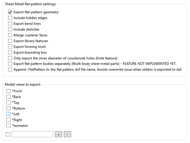
Sheet Metal Flat Pattern Settings
Select Flat Pattern Settings beside the main option to control which entities PDMPublisher writes to the DXF.
| Option | What it does |
|---|---|
| Export flat-pattern geometry | Exports the flattened outside profile, internal cutouts, and other visible flat-pattern edges. This is the normal starting point for a manufacturing DXF and is selected by default. |
| Include hidden edges | Adds edges that are hidden in the flat pattern. Leave this cleared for most laser, plasma, or waterjet workflows unless the downstream process specifically needs hidden geometry. |
| Export bend lines | Adds the bend lines from the SOLIDWORKS flat pattern so manufacturing can identify where bends occur. |
| Include sketches | Includes visible sketch entities from the sheet-metal part in the exported DXF. Use this for manufacturing marks or other sketch geometry that must accompany the profile. |
| Merge coplanar faces | Merges adjacent faces that lie on the same plane, removing unnecessary lines between those coplanar regions. |
| Export library features | Includes geometry created by SOLIDWORKS library features. |
| Export forming tools | Includes geometry representing forming-tool features such as louvers, lances, embosses, or similar formed features. The exact result also depends on the part's SOLIDWORKS sheet-metal document settings. |
| Export bounding box | Adds the rectangular bounding box around the flat pattern. This can be useful for estimating stock size or nesting. |
| Only export the inner diameter of countersink holes (Hole feature) | For countersinks created with the SOLIDWORKS Hole Wizard, exports the inner hole diameter and omits the larger countersink outline. This can provide cleaner cutting geometry when the countersink is created in a later operation. |
| Export flat pattern bodies separately (Multi-body sheet metal parts) | Reserved for exporting each sheet-metal body into a separate file. This feature is marked not implemented yet in the current dialog and should not be used. |
Append -FlatPattern to the flat pattern DXF file name |
Adds -FlatPattern before .dxf. Enable it when a drawing and its associated sheet-metal part can both export to DXF, preventing one output from overwriting the other. |
Tip
For a typical fabrication DXF, start with Export flat-pattern geometry and Export bend lines. Add sketches, forming tools, or the bounding box only when your manufacturing process consumes those entities.
Model Views to Export
The lower section of the dialog lets you export SOLIDWORKS model views to DXF. The predefined choices are:
| View | Direction represented |
|---|---|
*Front |
Front view |
*Back |
Back view |
*Top |
Top view |
*Bottom |
Bottom view |
*Left |
Left view |
*Right |
Right view |
*Isometric |
Isometric view |
Select the checkbox beside every view you want to export.
Important
Selecting one or more model views changes the export from a sheet-metal flat-pattern export to a SOLIDWORKS annotation-view export. If your goal is a manufacturing-ready unfolded profile, leave all model views cleared and use the flat-pattern settings above.
Add a custom view
You can also export a named view saved in the SOLIDWORKS part:
- Enter the exact SOLIDWORKS view name in the text box.
- Select the checkbox beside the text box if the new view should be enabled immediately.
- Select + to add the view to the list.
- To remove a custom view, enter its name and select -.
Custom view names must match the names stored in the SOLIDWORKS model. The standard views use their SOLIDWORKS API names, including the leading *.
Recommended configurations
| Goal | Recommended selection |
|---|---|
| Basic cutting profile | Export flat-pattern geometry |
| Cutting and bending | Export flat-pattern geometry and Export bend lines |
| Include manufacturing marks | Add Include sketches |
| Show formed features | Add Export forming tools |
| Record required stock size | Add Export bounding box |
| Avoid a drawing DXF filename collision | Enable Append -FlatPattern to the flat pattern DXF file name |
| Export a projected model view instead of the unfolded pattern | Select the required entry under Model views to export |
Note
The DXF file format does not need to be selected separately for this flat pattern feature.
The first eight geometry controls and the bounding-box control correspond to SOLIDWORKS sheet-metal DXF export options. For additional technical background, see the SOLIDWORKS IExportToDWG2 API documentation.